Line Follower Robot

Introduction
This line follower robot was designed and built as part of the “ME 8281: Advanced Control System Design-1” course. Its primary function is to serve as a flexible testbed for evaluating various control algorithms developed throughout the course, including pole placement, internal model control, linear quadratic gaussian (LQG), and Kalman filtering. The line following scenario is a widely used platform for testing and implementing control system theories due to its simplicity and scalability.
Design and Fabrication

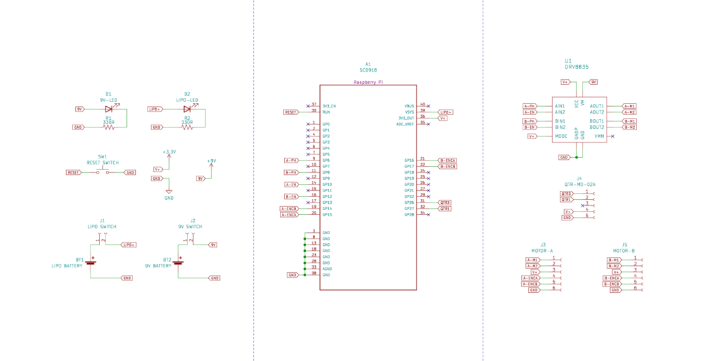
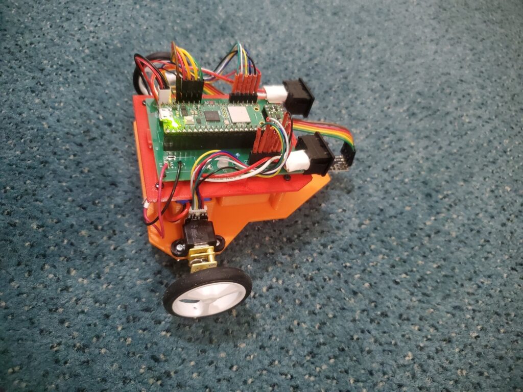
The heart of the robot is the Raspberry Pi Pico W board, chosen for its wireless data transfer capabilities. This eliminates the need for tethering the robot and allows for centralized computing on a separate machine, freeing up the Pico’s processing power. The design also incorporates:
- Two geared N-20 DC motors: provide the driving force for the robot.
- QTR-MD-02A reflectance sensor array: detects the presence and position of the line.
- DRV8835 motor driver: enables bi-directional control of the DC motors.
- Reset button: allows for easy reset and re-initialization.
- Status LEDs: indicate the power state of the two power sources:
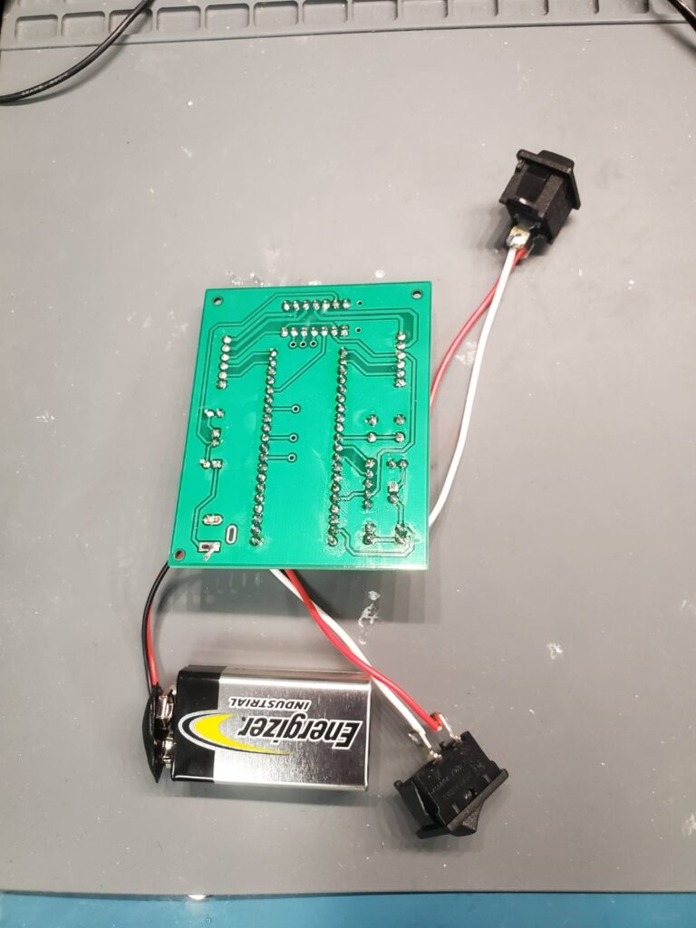
- LiPo battery: powers the DC motors.
- 9V Energizer battery: powers the remaining electronics.


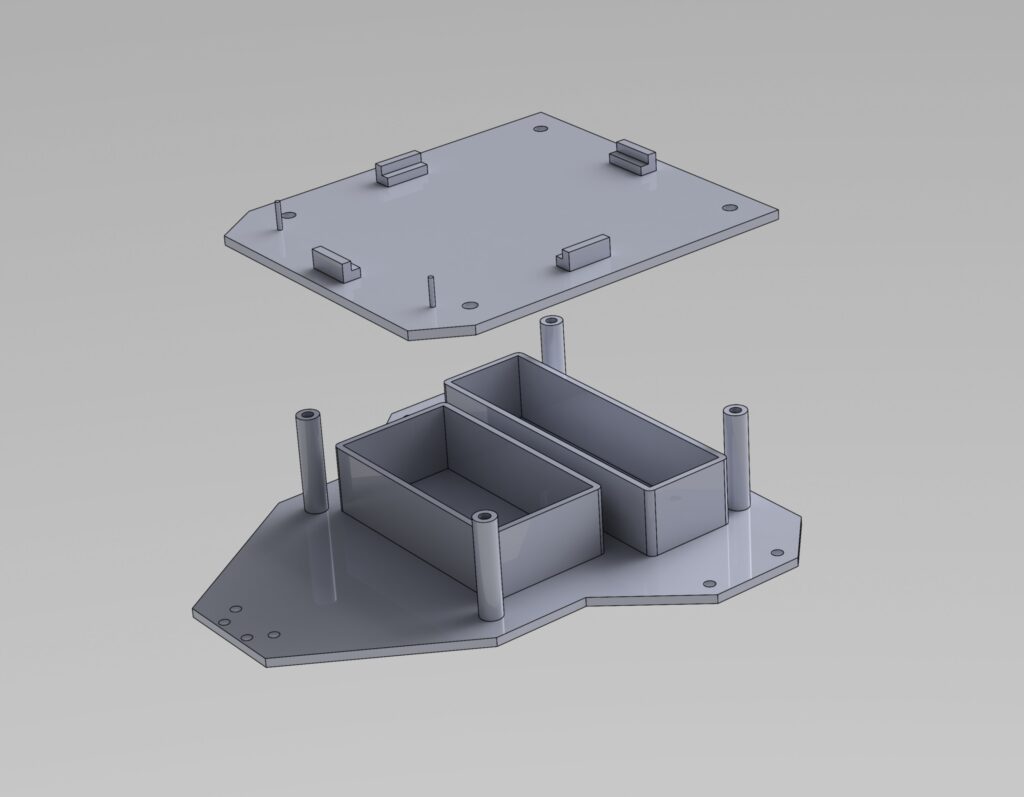
Schematic and PCB designs were created using KiCAD. The PCB fabrication was done through JLCPCB. The body of the robot was designed using SolidWorks.


Future Steps
While the hardware is complete, the developed control algorithms have not been implemented on the robot yet. The next phase will involve uploading and evaluating the various algorithms on the robot, allowing for practical validation and comparison of their performance in a real-world scenario.
Skills
- Circuit Design and Prototyping
- CAD Design with SolidWorks
- Electronics and Robotics
- Fabrication with JLCPCB
- KiCad

